Home |
Motorcycle Main page |
Links
Introduction
After the first head overhaul of my BMW R80GS in 1993 (at about 58 Mm), the engine behaved nicely throughout the next years.
However, having passed 130 Mm, oil consumption started to increase again. Yet it depended largely on riding style:
Riding 2-up towards Tuscany on the highway, the motor needed more than 0.5 liter oil for the 400 km.
I added some oil and for the next 1500 km there was no need to add anything more ... it seems that the high rpms on the highway
caused the excessive consumption: on the trip back I held the bike below 4500/min and oil consumption was "normal".
Anyway, since almost 90 Mm had passed since the first revision and I don't like the idea of carrying a jerrycan
of oil during holidays ;-), I decided to have the cylinder heads rebuilt again. The overhaul was done in 2007-04, at
146400 km and this page is a short recapitulation of the steps we took.
Many Thanks to Jürgen "Schorschi" for the great work and the occasion to document this with pictures!
Material |
Oil pan |
Disassembling the heads |
Machining new parts |
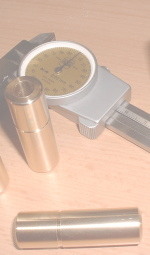
Compression |
Reassembly |
Notes
The following list enumerates the "particular" spare parts; prices are rounded and do not include VAT.
Note that this list does not include the the O-Rings, gaskets etc that are inherent to a head removal;
you can find that list on my R80GS page.
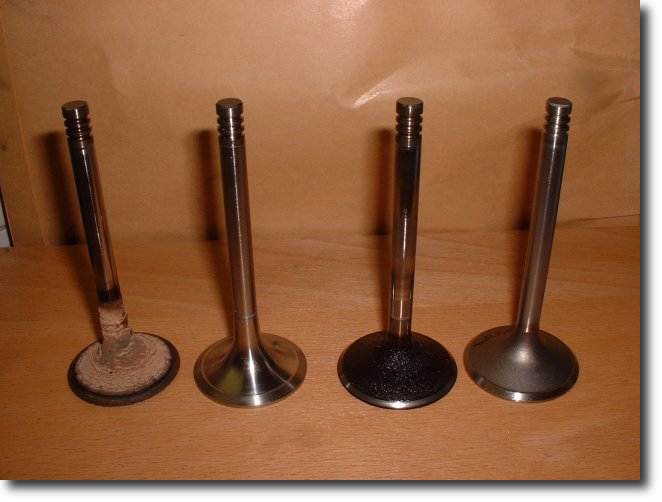
- 2 inlet valves (Kolbenschmidt), 33 €
- 2 outlet valves (Kolbenschmidt), 86 €
- 4 valve guides (BMW or tailor-made, see below; 60 €)
- 8 valve locks, (type?) 5 €
- 4 Seeger Circlips SW for diameter 14 mm
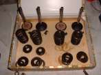
- 4 valve springs (BMW), 4.20 €
- 2 head gaskets (BMW), 23 €
- 2 valve cover gaskets (BMW), 8 €
Total material costs were about 300 €, not counting the number of hours we spent ...
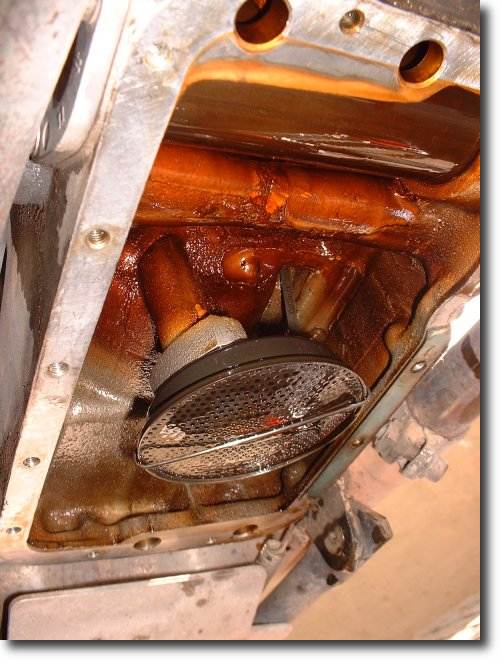
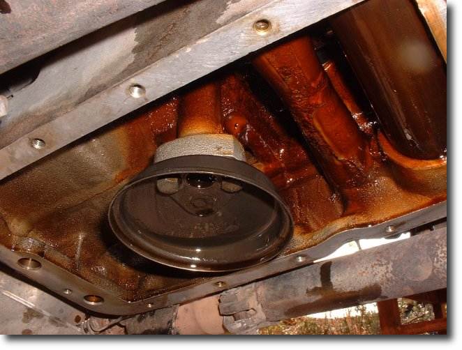
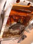
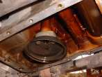
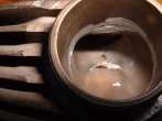
Upon arrival, we drained the oil. Since there have been many reports of BMW airheads owners finding some metallic pin in their oil pan,
I removed the oil pan of the GS, too. No metallic parts, no foreign body present, so I cleaned the pan and the oil sieve, then reassembled
the whole thing again. To prevent leaks of the joint, the bolts holding the oil pan should be tightened down with a torque key; 10 Nm.
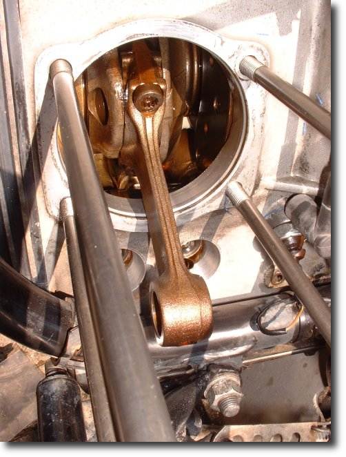
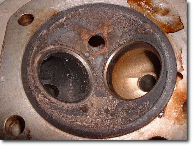
A thorough visual inspection of the engine did not reveal any signs of excessive wear. All four pushrods were like new.
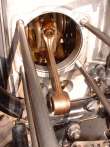
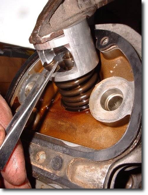
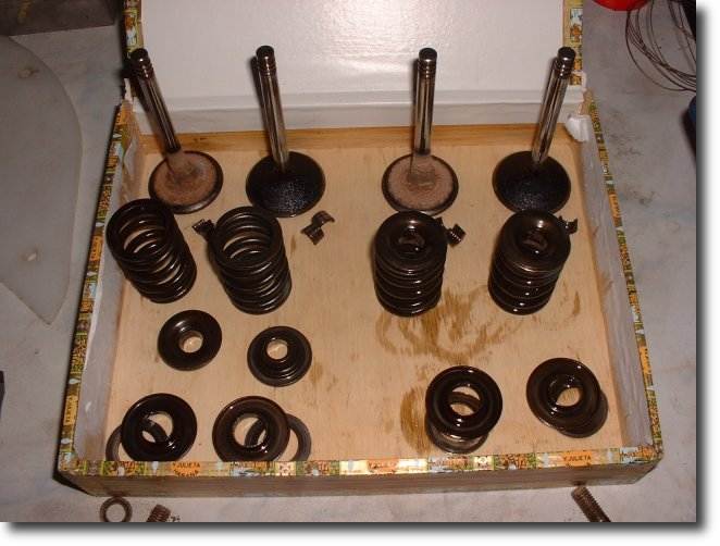
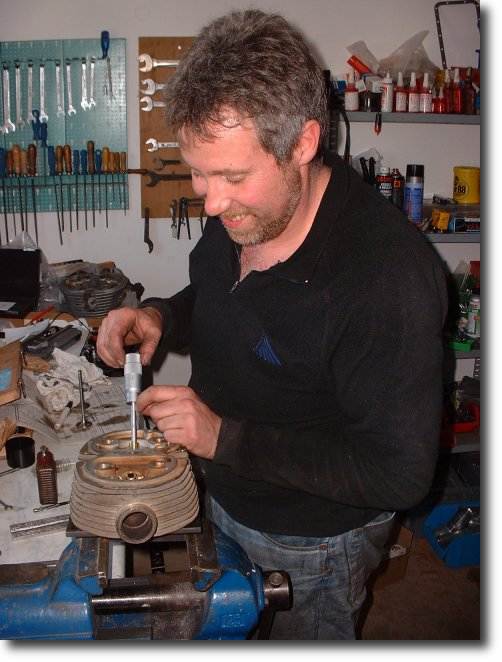
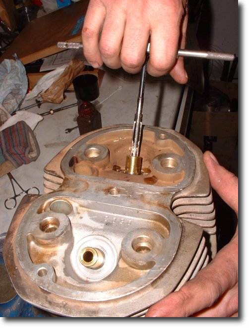
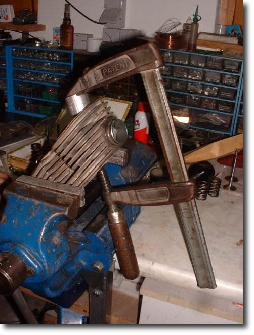
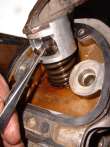
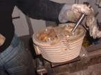
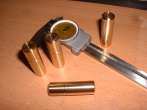
The removal of the heads is described on my R80GS page. Once the heads were on the bench, a
spring pocket is put over the valves; it allows to access (and remove) the valve locks ("Ventilkeile") while
the spring is compressed. Once the valve locks are removed, the valves can be removed easily.
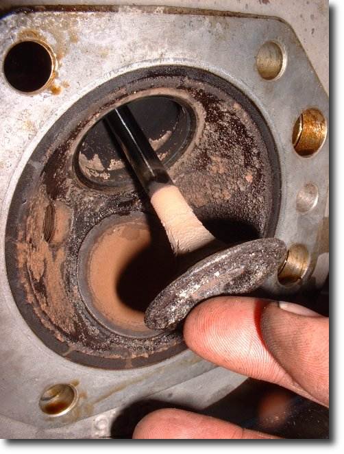
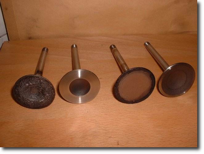
As in the previous revision, we found that all four valves had considerable play; the valve guides were worn out with an oval shape.
This is "normal" wear and is inherent to the OHV engine, but is also the cause for a regular head overhaul.
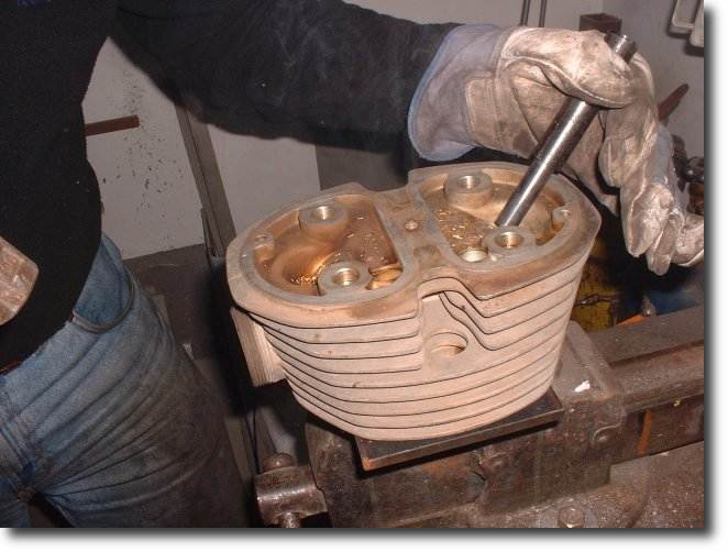
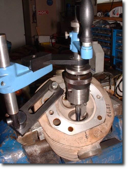
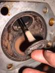
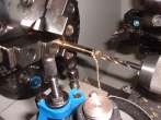
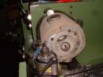
Before the new valve guides can be machined, the old ones have to be removed. Since they are tightly fitted into the heads,
this is commonly done by heating the heads to about 240°C and then driving the guides
out with a hammer.
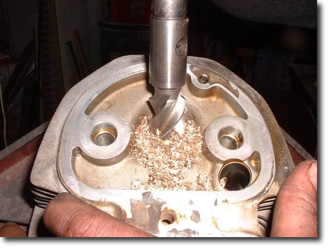
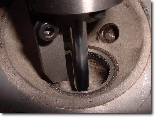
The job is greatly facilitated if the old guides are machined down to their base before;
in particular the steel C-clips have to be removed since they would prevent the removal completely.
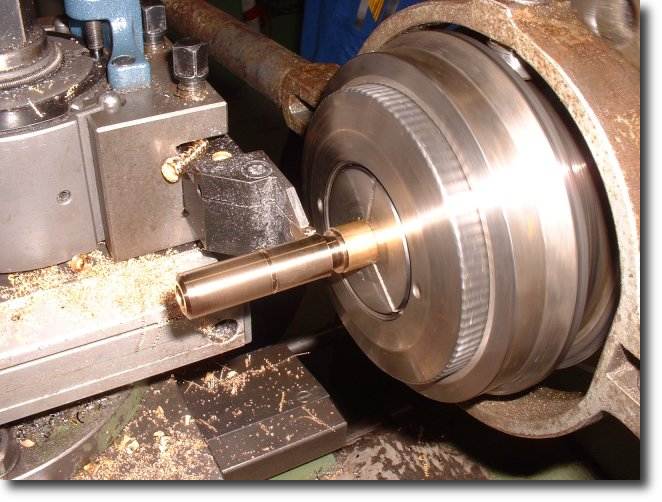
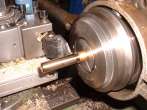
The new valve guides were not just bought from BMW but tailor-made. The material used was Brass CuZn37Mn3Al2PbSi (ex CuZn40Al2 R570),
material number CW713R (ex 2.0550).
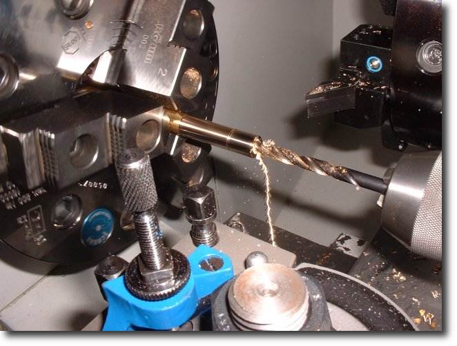
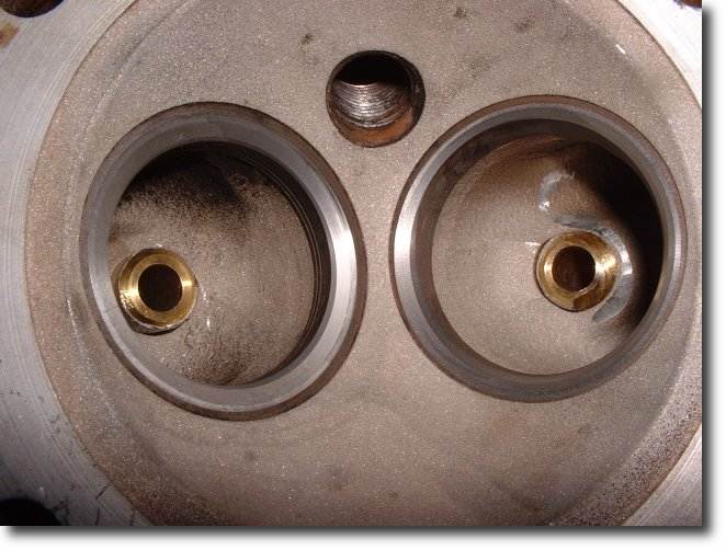
The four valve guides were machined and drilled to fit the four valves individually,
which means that we took differences in the range of 0.01 mm and below into account. BMW factory tolerances are much higher.
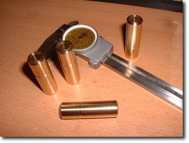
The rough dimensions of the valve guides are: OD 14 mm (but: measure the actual diameter of the hole and add 0.03...0.04 mm);
ID 7.8...7.9 mm (will be refined later), length 50 mm.
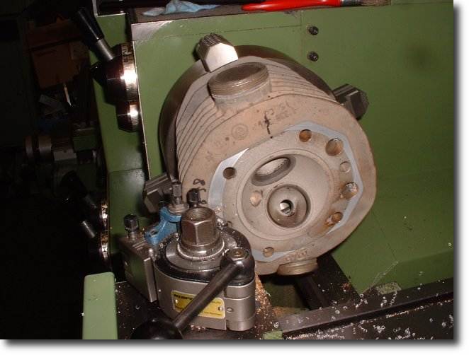
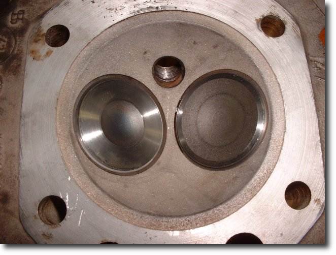
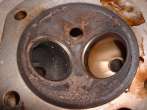
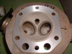
Since I wanted a better fuel economy (and a bit more power ;-), a slight increase in compression would be beneficial.
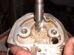
Thus, we sand-blasted the heads carefully, then machined about 0.5 mm off the heads
(but I deliberately stay with the 800-ccm engine). It should be noted that this is preferably done after the new valve guides
are installed (see below), since the heating usually induces some warping of the heads.
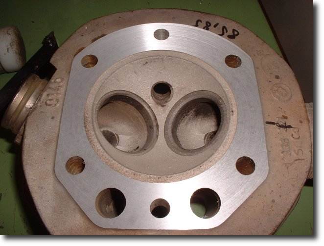
In the same context, irregularities in the heads were carefully smoothed with a grinder. This concerned especially the
newly-inserted valve guides (next day), but also the inlet area where the carburetors are fitted.
Some complications came after we fitted the heads to the bike and started the engine. It started fine, but there
was some odd noise and after a few seconds ... oil started to leak out at both head gaskets!
I shut the engine off immediately. Frustrated, we started to search the error. We had used new gaskets, the torque wrench
was reliable, everything fit nicely - so why this leak and on both cylinders at the same time?
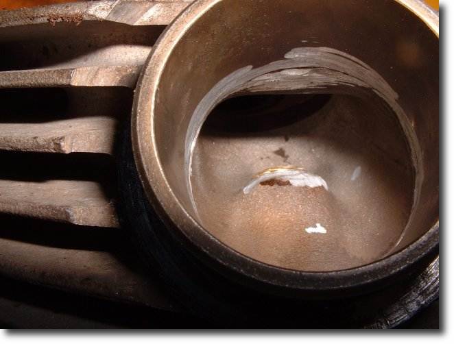
It took us two head install-and-removals until we found the reason. To cut a long story short:
The 800-ccm cylinders - and only these, not their 1000-ccm counterpart! - have a little "edge" that protrudes slightly into the cylinder head.
If you take material off the heads (which is what we did), this "edge" will touch the head and consequently, the head gasket
is no longer compressed. Thus, if you machine the heads, be sure to take the cylinders along to the machine shop, too ;-)