Home |
Motorcycle Main page |
Material |
Theory |
Installation |
Testing |
Links
Introduction
So you wonder why you'd want to use heated grips on your motorcycle?
Well, even if you ride only in summer I'm sure you already were in
situations where you wished you had warmer fingers. Such as a
ride in the evening, over a pass in the mountains, or in a downpour
when your gloves got wet and you did not have those warm spare gloves
with you.
I started building my first set of heated grips when I got my Suzuki
GSX250E and at that time the motorcycle was my only means of transportation
(poor student that I was ;-). Since then, most of my motorcycles have been
equipped with this "extra".
Today, you can buy heated grips at motorcycle accessory shops and several brands
may deliver them even ex factory with this accessory. For those who want to
build their heated grips themselves, here are some hints.
Material
A heated grip is nothing else than an electrical wire that is embedded
inside the rubber of the grips of the motorcycle. If electrical current
passes through the wire, it gets warm just like any electrical heater
you use in your house.
In the design described below, I have wrapped such a wire around the grips of my motorcycle and fixed them with heat shrink tube (german:
Schrumpfschlauch, french: thermoretractable).
The wires are then connected to the electrical system of the motorcycle (switched +12 V on one end, ground on the other).
A switch allows to turn them on and off and another position of this switch allows to use a setting with reduced heating power.
Of course you can also use an electronic regulator :-)
First of all, I assume that you have some practical experience with
maintaining your motorcycle. You should be able to read electrical
wiring diagrams and to find which cable is located where.
The usual disclaimer: These are things that I did myself on my own
motorcycles. Most of it should also be applicable for other models,
but if you repeat this with your bike, you do it on your own risk.
You will need the following material (the "why and how" are discussed
in the text below):
- a length of Constantan (german: Konstantan) wire, preferably of 0.4 mm diameter and about 1.5 m per grip
(if you use another diameter and/or another wire material, you will need a different length.
For the calculations see below).
If you have trouble finding Constantan wire, look in an electronics catalogue under "resistance wire" or try a school material supplier:
Constantan wire is used quite often to demonstrate Ohm's law.
- Two pieces of heat shrink tube 125 x 50 mm, preferably with thermal glue.
The type I used was IMCS-A 50/18 mm, which costs about 30 CHF per meter if you buy small quantities
(many thanks to Christoph Buehler from Rotima in Switzerland for directing me to a suitable material!).
Basically any rugged shrinking tube with thermal glue should do the job.
- A ceramic resistor 2.2 Ohms/20 W, or a suitable length of Constantan wire that is wrapped into isolated tubing.
- A small On-Off-On switch than can switch at least 4 A and be attached to a suitable place on the bike.
- As an alternative to the two items above: an an electronic regulator.
- A few meters of thin, highly flexible coaxial cable such as RG174. Although there is no "technical need" to use coaxial cable (you can use
any cable that you have at hand) I found it more practical - and more elegant - to feed a single cable to each grip.
- Some standard cables, cable binders, self-adhesive textile tape, and a few crimp-on electrical connectors for car/motorcycle electrics.
As for the tools, you will need a good multi-tester, an electrical
soldering iron (40+ W recommended), a heat gun and the usual tools
for cutting wires.
In the first trials I thought of using copper wire for the heater
winding, but found that the typical resistance of copper is too low
- it would require either a very fine (read: fragile) or a very long
(read: not practical) wire. I found that Konstantan is a very suitable
alternative: Konstantan is a Cu/Ni alloy with a fairly high typical
resistance, does not change its resistance with temperature (hence
the name), is mechanically robust and can be soldered with a standard
soldering tool.
By the way, Konstantan/Copper makes a nice thermocouple with a
pretty large EMF. Thus, if you want to measure the temperature of your
engine, why not take a copper and a Konstantan wire and crimp them
together at the tip?
Calculations
The power requirements for heated grips depend on the ambient temperature
and on your individual perception. I found that a maximum power of
about 25 W per grip is probably sufficient for all situations. A
second setting with reduced power of 8...12 W is suitable to keep
your hands warm under not-so-cold conditions and of course you may
also introduce a variable power control to adapt heating power to
all situations (see below).
At the same time, power consumption should be low enough not to thread
the rest of the electrical system of your motorcycles. Two grips with
25 W each correspond roughly to an auxiliary headlight and should be
compatible with almost any modern motorcycle.
I wired both grips in parallel. This has the advantage that if one grip fails
(for whatever reason, such a a broken wire inside the winding), the other remains
functional.
The required length of the wire depends on its material and its
diameter. What is needed is to have the "right" resistance to get
the desired heat dissipation per grip.
The calculation of the required resistance is simply done using Ohm's
law (R=U/I) and the definition of electrical power (P=U*I). Combined
they give the formula to express the dependance of power from
voltage and resistance, P=U2/R.
Thus, to consume about 25 Watts, use a length of wire that
has a resistance of roughly 5.8 Ohms per grip.
Please note that the exact resistance does
not matter that much; you probably won't feel if it's 23 or 26 Watts.
I build my heated grips with Konstantan wire of 0.4 mm diameter,
which has a resistance of 3.9 Ohms per meter. Using a length
of 1.5 m of the above Konstantan wire per grip yields a power
dissipation of 25 W at 12 V and of 31 W at 13.6 V.
For the "reduced power" switch setting, the calculation is the
same, but the two grips are switched in parallel and then in series
with an additional resistor. With a 2.2 Ohm resistor, the
remaining heating power on the grips is 8 W at 12 V and 10 W at
13.6 V. The heat dissipation of this resistor is
about 16 W, so do not use standard carbon resistors. Ceramic
resistors are designed to get pretty hot without failing and they are cheap.
Some manufacturers use a resistance wire that forms an integral part of the
hotgrip wiring - also a nice way to dissipate the heat over a large area!
A much more elegant solution to control the power to the heated grips is an electronic regulator
based on a pulse modulator. In this setup, an oscillator switches a transistor "on" and "off"
at a frequency in the lower-Hz range (reportedly, higher switching frequencies can lead to
interference with some equipement). I sell suitable control units here.
Putting it together
A mechanical problem is related to the movement of the right grip,
which is of course used to control the throttle. A very flexible wiring
should be used here and I have used a thin coaxial cable of the RG-158
type (standard RG-58 is too thick). Both grips are prepared in the
same way:
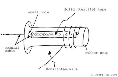
Drill a small hole on the "inner" end of the grip, so that you
can pass the coaxial cable through it. Cut out a small slit in the
rubber of the grip so that you can hide the coaxial cable in there
- otherwise, you will always feel that cable later on and I can assure
you that this is not what you want ;-).
Feed the coaxial cable through the hole. Remove the outer isolation of this
cable so that the shielding is located at the "inner'' end of
the handle and the inner ("hot'') wire goes to the outermost
end of it. Press the cable in the slit described above and attach
it with a length of textile tape (use textile tape, no plastic).
Cut the required length of Konstantan wire. Solder one end to the
"hot wire" of the coaxial cable. Konstantan can be soldered
with standard electronic solder, but soldering surfaces should be
perfectly clean.
Now start wrapping the wire around the rubber grip. You may want to
use a short piece of textile tape to attach the winding from time
to time.
Make a node in the wire to fix the last winding, then solder it carefully
to the other end (shielding) of the coaxial cable. Use an Ohmmeter
to verify that you have the right resistance - neither a short circuit,
nor an open winding.
Now use a suitable piece of thermo-retractable tubing to fix the whole
assembly. You will need a heat gun for this; I do not recommend using
an open flame! Initially I used some cheap, thin tubing, but this
tends to get brittle over the years. Recently I replaced it with some
thick-walled tubing that is additionally equipped with a layer of
thermal glue - that is, when you heat the tubing it shrinks and the
glue melts, fixing the whole assemble very neatly to the grips. This
reduces mechanical stretch to the wires and it provides additional
protection by excluding water (due to the glue). The type I used was
IMCS-A 50/18 mm.
Practical notes
- I strongly recommend to start wrapping from the "outside" of the grips,
as described above: It is easier to solder the resistance wire to the
coaxial cable first. You can then wrap the wire, finally fix it with a node
to the shielding and then calmly solder it. If you proceed the other
way round, you will need more than two hands ;-)
- Another trick is to solder each end of the coaxial cable to a short length
of standard wire ("Schaltdraht") first and then to use these two pieces of wire
to connect to the Konstantan wire. This avoids potential trouble with the "soft"
isolation of many coaxial cables.
- When finished, the cables are fed "below" the grips and from there
they are simply attached to the existing tubing that holds the motorcycle's
wiring. If you use black wires and cable binders, they will be almost
invisible.
Once you have finished wiring the grips and verified the electrical
values, it's time to hook up the whole thing to the electrical system
of the bike. Disconnect the ignition (better: the the battery) while
you do this installation!
Connect the two shield wires of the coaxial cables together and do
the same with the "inner" wires. Verify the resistance again;
you should get half the value you measured above as both are now
used in parallel.
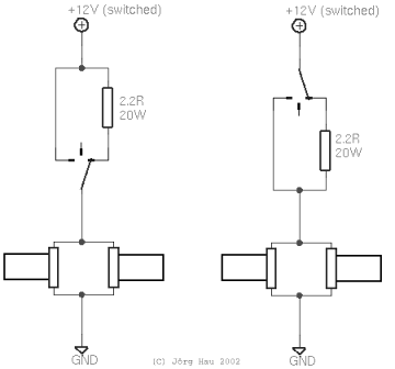
The wiring is shown in the diagrams; there are at least two alternatives
possible. Select the one that fits your needs.
Practical notes:
- Connect the shielding of the coaxial cable to ground (Kl. 31) and connect the
"inner" wire to the "hot" line. If ever the cable isolation is worn off,
this will avoid a short circuit with the frame.
- The +12 V line (Kl. 15) must be a fused
line that is switched with the ignition. My BMW R80GS
has a suitable circuit that is also used for the auxiliary plug (under the
seat) and that is fused with 7.5 A. The "deluxe" version is to
use a relay that is switched with the ignition and that provides
+12 V to the grips.
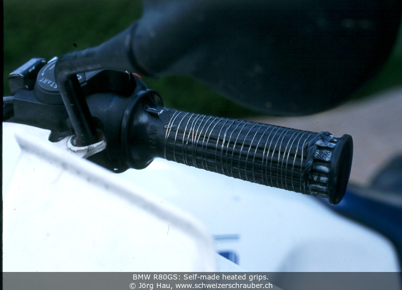
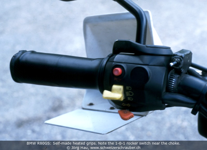
- The On-Off-On switch must be able to switch 4 A. I used a
small switch that I packed into a small, home-made aluminium case,
sealed with epoxy glue and that is in turn attached to the left
handlebar of the bike - see the picture above.
- The 2.2 Ohms power resistor is electrically isolated and is mounted
on a well-ventilated place close to the frame under the gas tank.
Now you are ready to test. Re-verify everything, reconnect the battery,
and turn the ignition on. If you switch the grips on, you should note
that they get warm after a few seconds (it may take a while).
Keep in mind that the diameter of your handlebars has now changed,
due to the wall thickness of the shrinking tube. Be aware of a somewhat
changed "feeling'' for you bike when you ride it the first few
times now. In addition, the "grip'' of the handlebars has changed
- this is no longer rubber but rather smooth plastic. Personally I
did not have problems with that, but if you use nylon gloves to protect
you from rain you may encounter the problem that the throttle grip
might slip somewhat under your gloves. You have been warned.
What else remains to say? Have a good season, whatever the weather
may be!
