This is a simple device that can be used to monitor the battery voltage in a motorcycle or in a car.
I developed this circuit since I encountered a number of charging system failures that occurred without a "visible" warning.
Typically, most japanese motorcycles do not have a charge control lamp at all.
Even on bikes that are equipped with such a lamp (Bosch system, e.g. BMW and Moto Guzzi), defects may still occur in a manner where the "idiot light" may not light up in due time.
The circuit presented here is a simple means to overcome this problem.
I offer these units for sale. If you are interested in buying one (or more ;-), follow this link.
The device is used to monitor the battery voltage continuously: As long as this is around
13.6 V (± about 0.8 V), the charging system is very probably working properly.
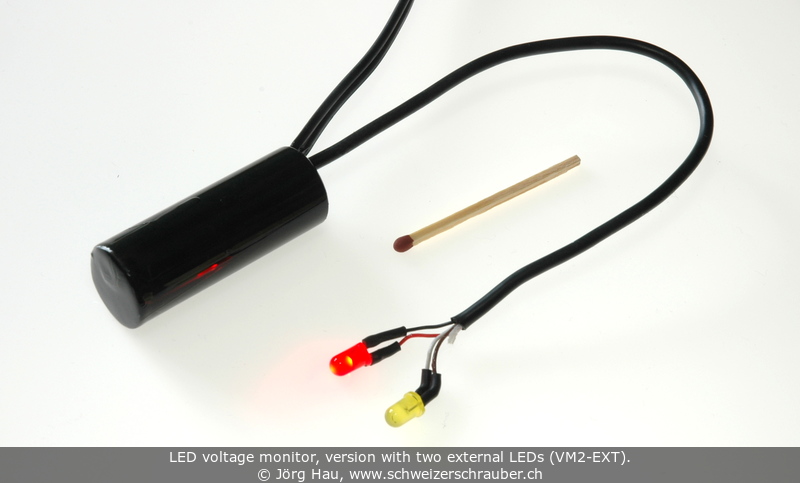
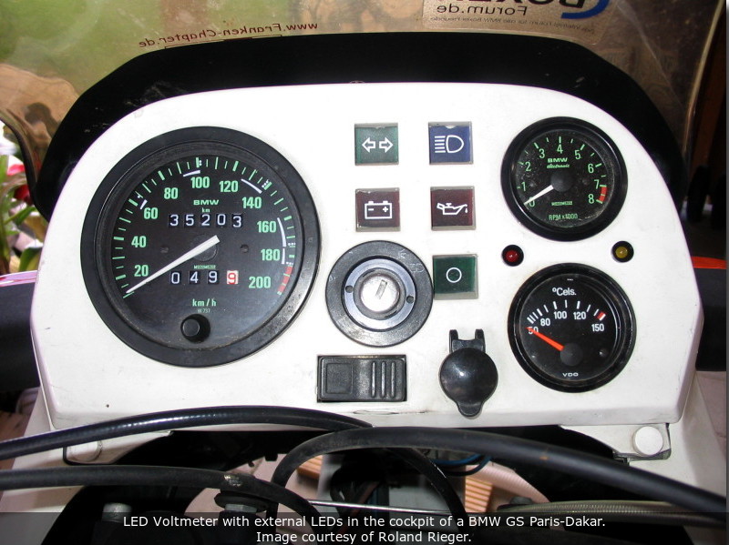
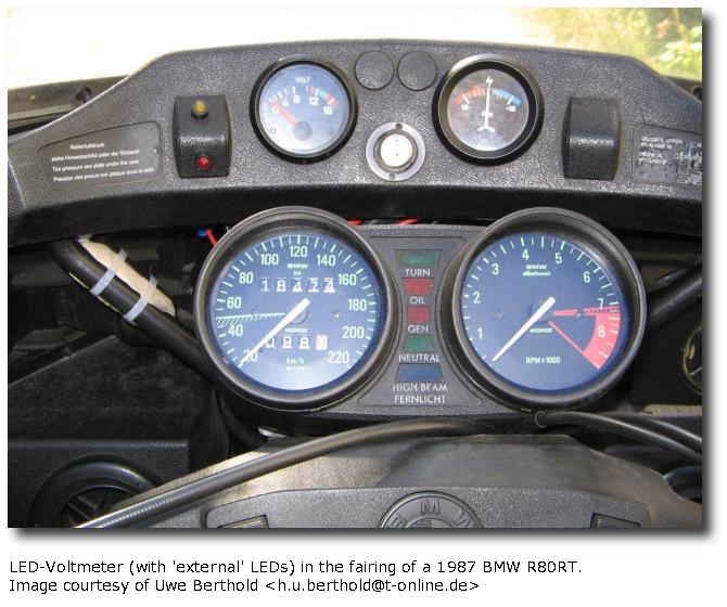
The circuit itself is of a rather minimalistic design, with only two LED to indicate the actual voltage range.
A red LED is used to signal a voltage that is too low to charge the battery (usually a sign for alternator failure),
and a yellow one that indicates overvoltage (usually due to a defective voltage regulator).
Thus, it is more a "voltage indicator" than a "voltmeter". Here are two short videos:
Why only two LED?
There are many circuits available that use e.g. three, five or more LED to indicate the actual voltage.
However, all I want to know is if the voltage at the battery is in the right range to keep the
charge up - if yes, I do not want any control light shining at me: "No messages are good messages" ;-)
The particular design shown here has a number of advantages:
The voltage display is instantaneous - faster than any conventional (analog or digital) instrument!
It is an efficient, real-time diagnostic tool that allows to track even short dropouts.
The 2-LED display is simple to understand. In contrast to this, the display of any analog or digital voltmeter must be read,
understood and interpreted - which would take your mind off the road.
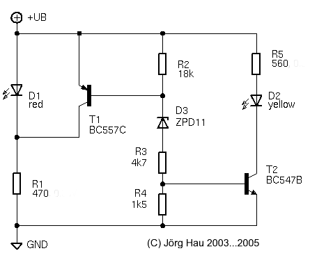
When a (low) voltage is applied, LED D1 simply lights up as current flows through it; R1 serves as current limiter.
If the voltage applied to the circuit reaches some 12 V, the Zener diode D3 will start to conduct.
The current through D3 causes a voltage drop across R2 which will open T1 and in turn will "cut off" the voltage across LED D1.
At this point, no LED is lit ... which should be the standard condition with a healthy charging system.
If the voltage increases further (above 14.5 V), the voltage drop across R4 will be large enough to open T2, which makes LED D2 light up.
The accuracy of the circuit depends on the chain along R2, D3, R4, T2 and R4.
Typically, with the values indicated in the circuit diagram above, the red LED starts to fade around 12.1 V and is completely off at 12.6 V.
The yellow LED starts to glow at 14.5 V and is fully lit at 15.0 V.
- Note that R1 and R5 are dimensioned for 20-mA LED.
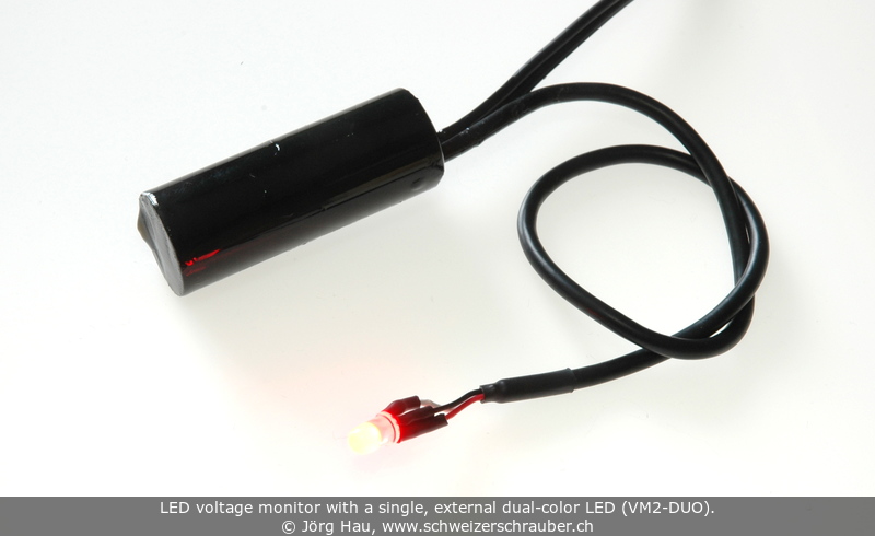
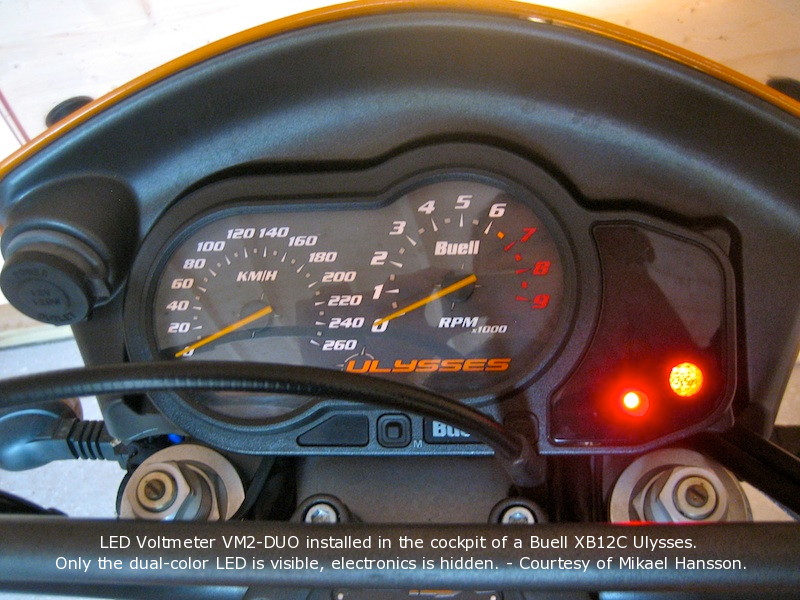
Please note that I have improved and updated the circuit several times, e.g. to accomodate dual-color LEDs.
However, due to violations of my simple license terms, I decided not to share the improved versions anymore - if you want it, you have to buy it from me.
Please send complaints to the people that copy my design without asking and sell it e.g. on ebay - !
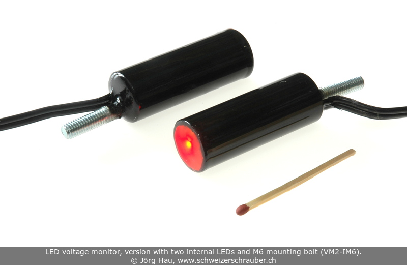
The parts can be soldered onto a small piece of breadboard, or you may make a PCB for it. For protection against vibrations,
humidity, dust etc., I placed the PCB in a piece of plastic tube and sealed it in epoxy resin. The M6 bolt is simply embedded into the resin.
Please note that this is an extremely simple set-up. There is no protection against inverted polarity,
and not even a fuse, so you must connect it to a fused line.
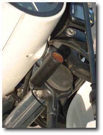
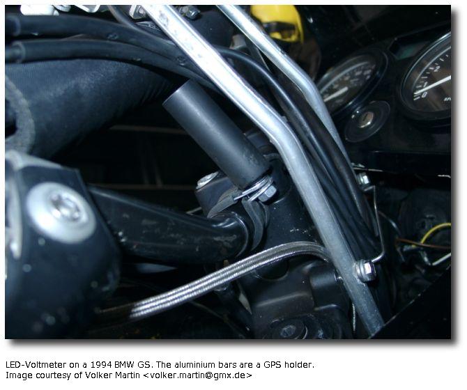
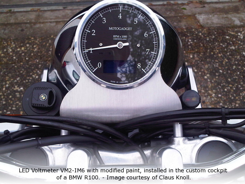
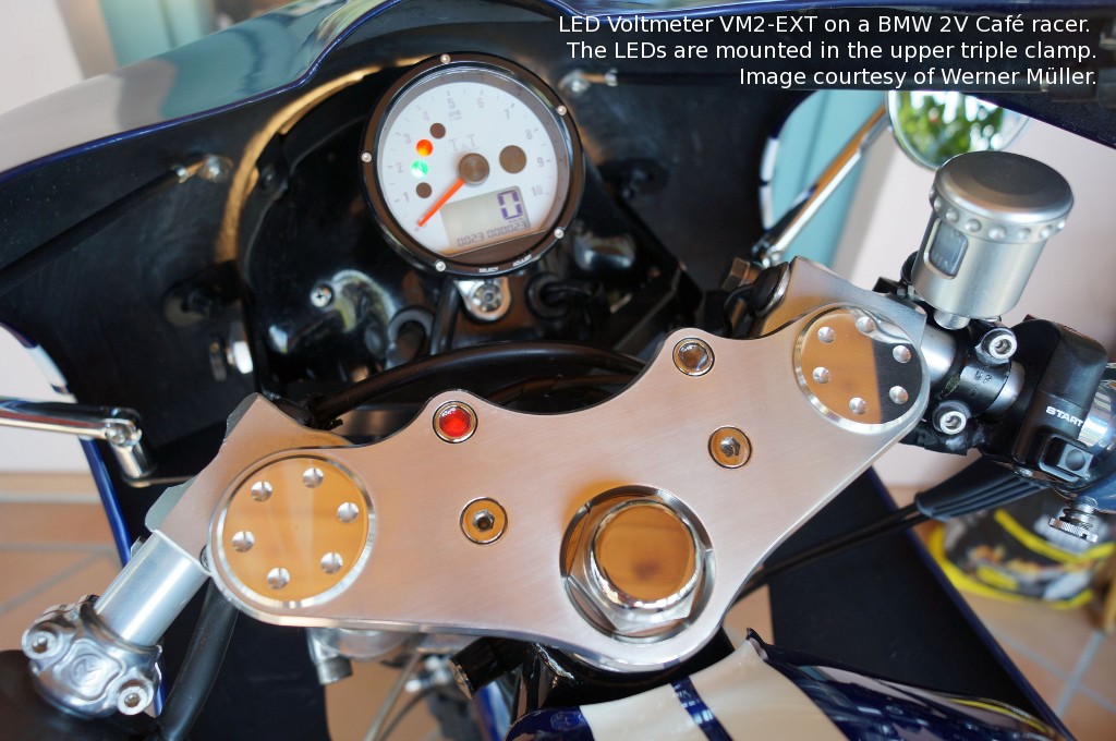
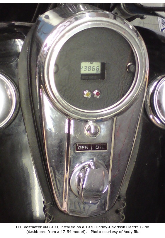
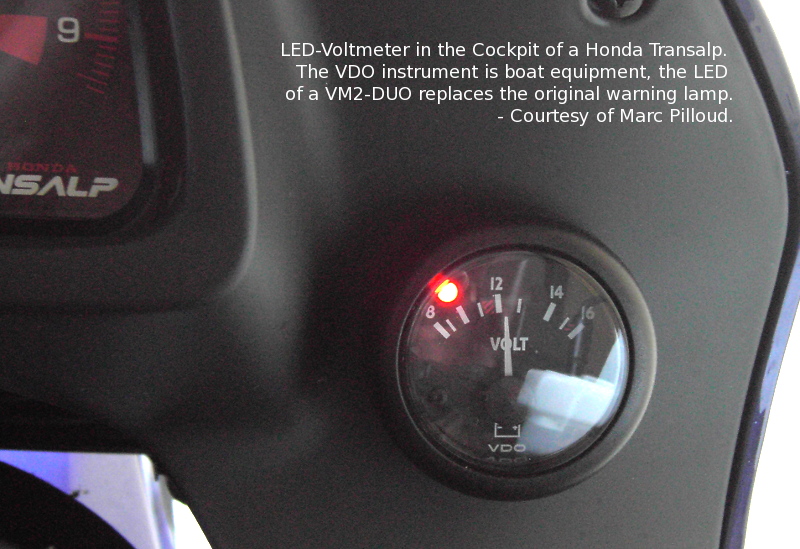
There are many possibilities to install this device. One version is equipped with an M6 bolt on its back so it can be attached "almost anywhere".
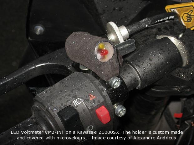
A common possibility is to use a simple clamp to attach the voltage indicator to the handlebar.
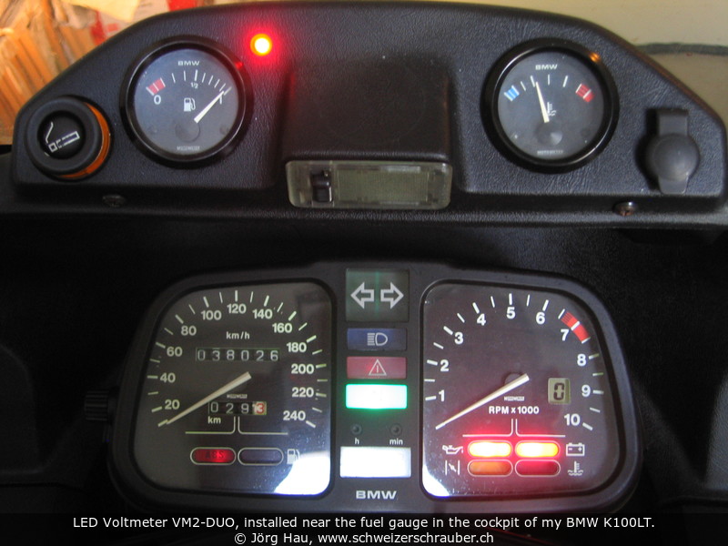
On the early BMW R80/100GS and G/S, the device fits nicely to the "clamp" at the upper end of the left fork that was supposed to hold BMW's chronometer.
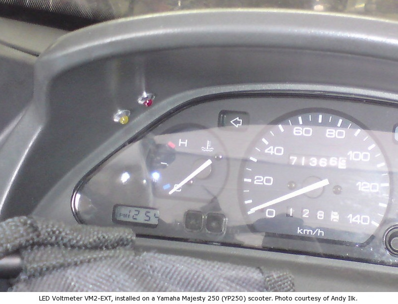
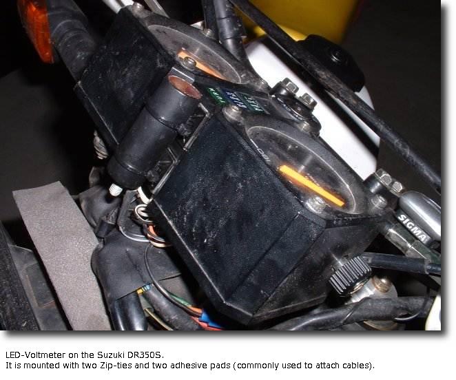
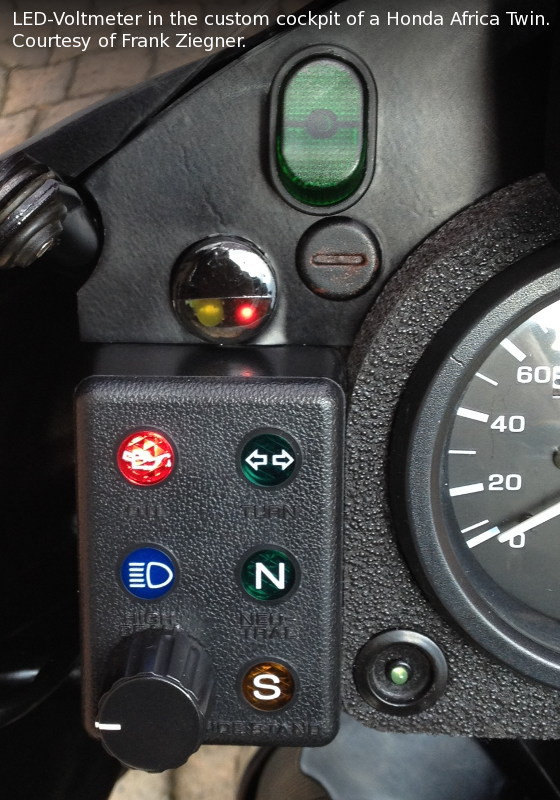
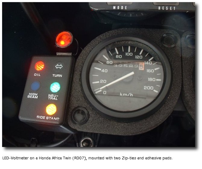
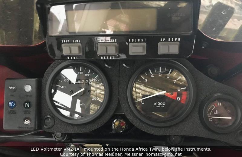
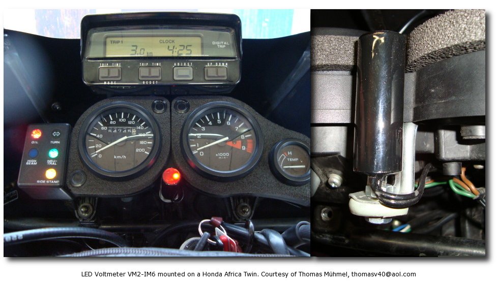
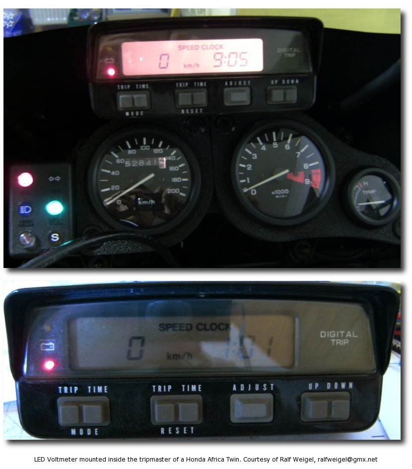
Another possibility is to take a pair of Zip-ties and attach it above the instrument cluster; I did this e.g. on many Honda Africa Twin (where access to the two required electrical connections is truly easy) and on my Suzuki DR350.
Function test: When the ignition is switched on, the red LED usually lights up since the battery is not charged.
After starting the engine the red LED should go dark slightly above idle. - There is no such test for the yellow LED.
Normal operation: In normal operation all LED are off. A dim "glow" (where both LED appear to be dimly lit
with approximately the same intensity) is normal on many Japanese motorcycles: this is due to the particular
voltage regulation that is used on these bikes; their charging system creates a rapid sequence of over- and
undervoltage spikes, which will cause the two LEDs to light up dimly in rapid succession.
This phenomenon is not observed with a Bosch system.
Red LED: The red LED indicates that the voltage is too low to keep the battery charged.
With many motorcycles this is normal at idle (in particular BMW airheads, where the red LED
"pulses" due to the pulsating current drain of the ignition. The Bosch charging system starts to work
'reasonably' at about 1500/min.).
However, if the red LED lights up while driving this indicates potentially a defective alternator,
or at least excessive load on the charging system. In case of breakdown you may help yourself provisionally
by switching off all electrical consumers and carefully riding to the next workshop on battery power.
Yellow LED: The yellow LED indicates that the voltage in the electrical system is too high.
In most cases this is due to a defective alternator voltage regulator, or a defective connection
leading to it (hint: ground wire on Bosch systems; connector with the 3 yellow wires on Honda Africa Twin).
In this case, the electrical and electronic components of the electrical system are in danger since
the voltage can exceed 40 V: Do not ride the bike in this condition!
In case of breakdown you may help yourself provisionally by disconnecting the voltage regulator
and/or the voltage regulator and carefully riding to the next workshop on battery power.
Ever since I started producing the first units in 2002, I keep getting requests about them.
Your demand triggers a constant production, where every single unit is carefully manufactured, tested and finally dispatched in the different versions shown above.
As of mid-2018, more than 1000 units have been distributed to motorcyclists and to motorcycle manufacturers (!) all around the world. Thank you!
If you are interested in buying one (or "some" ;-), simply follow this link.
For those of you that ride Very Old School bikes, a 6-V version is available.
And for those who drive a truck, Unimog or camping car, a 24-V version is available, too.
Due to the low demand (less than 1% of all orders), these versions are only produced upon request: please allow ~3 weeks for delivery.
This information is provided in the spirit of "open design". The concept is similar to that of open source software:
It is available in "source form". Here, this means that I am making the design information freely available and you
may use this information to build your own systems for personal use, free of charge.
However, if you wish to develop some commercial product ("make money with it") based on the information provided here,
I require that you seek a license from me first.
The usual disclaimer: These are things that I did myself on my own motorcycles.
Most of it should also be applicable for other models, but you do it on your own risk.