Home |
Motorcycle Main page |
Links
Introduction
This article describes a home-made voltage regulator for Bosch charging systems,
with a cost of less than 10 Euro for the parts.
This regulator is designed for my BMW R80GS, but it should
fit all BMW "airheads" and almost all Moto Guzzi, as well as all car or motorcycle charging systems
where the field winding is connected between DF and D- (see below).
The usual disclaimer: These are things that I did myself on my own motorcycle.
Most of it should also be applicable for other models, but you do it on your own risk.
Now what does a voltage regulator do? Well, it connects the alternator
rotor to the power supply - the battery - until a pre-set voltage is reached,
then it switches the voltage off. That's all!
For an in-depth discussion of the Bosch/BMW charging system, have
a look at
Jim Buchanan's pages (link seems to be dead?), maybe also at a similar page at
thunderchild-design.com.
In short, the generator of the charging system generates an alternating
current that is rectified by diodes (hence the famous "diode board"). As the
generator rotor turns with the engine, its output voltage depends on -
and changes with - the revolutions of the engine. However, we do not
want a changing voltage: Things like electronics, battery and light prefer
to run with a rather regulated voltage of about 13.6 V.
This is achieved in a simple manner: As soon as a pre-set voltage
is reached, the regulator switches the field winding off. If the voltage
drops below the setpoint, the regulator switches on again and the cycle
is repeated. This leads to very fast switching, which in turn leads to
a pretty good regulation of the voltage.
Note that an automotive voltage regulator does not operate like the "three-pin regulator"
that you may know it from standard electronic power supplies. The latter hold the voltage at their output constant,
while a car regulator switches its output voltage completely off. In early years, voltage regulators were
indeed electromagnetical devices, working similar to relays.
Design
The circuitry used here is rather simple. It was inspired by an article from W. Marton that appeared in
Elektor 9/1992, pg. 64-65 and was improved after fruitful discussions with Matthias Otto (Thank you, Matthias!).
Please note that this page is about the regulator, not the "rest" of the charging system
- thus the right-hand side of the schematic shown below is largely simplified; in particular the diode board has been omitted!
For a detailed plan see Jim Buchanan's pages (link seems to be dead?).
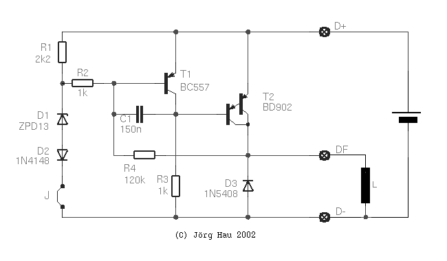
D+ and D- are connections to the positive and negative battery poles, respectively,
and are used to "sense" the voltage at the battery. DF is connected to the field
winding L, which is the alternator's rotor winding. In the charging system as used
in BMW "airheads", the other end of the rotor is connected to ground (D-).
T2 is a Darlington-type switching transistor which determines the current through the alternator's rotor winding.
As long as the input voltage is low, D1 is not conductive, so T1 gets tied up to the positive line and will behave
like an open switch. In this state, the base of T2 is connected to ground via R3 and T2 is conductive: current flows
through the rotor winding L and the magnetic field in the alternator increases, which in turn increases its output voltage.
When the voltage is high enough to bring D1 in its conductive state, T1 will also become conductive and will connect
the base of T2 against the positive line. T2 will close, the current through the alternator rotor is reduced, the
alternator voltage drops and the cycle repeats. You get the idea.
The switching voltage of the circuit is determined by the Zener voltage of D1 plus the voltage drop over D2
plus the base-emitter-voltage of T1. Theoretically this is 14.2 V (14.0 at DF) but it will vary somewhat
with temperature and the production variations of the Zener diode.
With only T1 and D1 but without D2, the switching voltage would be 13.6 V.
As the standard BMW voltage regulator has a setpoint of 14.0 V (giving 13.6 V at the battery),
I've added D2 for fine-tuning. This results in a switching voltage of 14.2 V and thus, expectedly, 13.8 V
at the battery. This is about 0.2 V higher than the standard voltage and corresponds also to the setting of the
mechanical regulator on my R100TIC.
In the first prototype I provided a jumper J (wire) between D2 and D3. You may use this to add another diode in series with D2.
If a Ge type is used, this will add further 0.3 V - a feature that may be used to build a simple "adjustable" voltage regulator
which can be switched between "standard" (14.0 V) and "fast charge" (14.3 V) mode.
A silicon diode would provide +0.6 V, but this will be too much for a standard lead/acid battery if used in the long run.
Note that the version shown above does not have any protection against overcurrent.
Instead, the paper that inspired me to this circuit had a 0.18 Ω resistor in series with T2.
A motorcycle or a car is a pretty nasty environment for electronics: it is full of vibrations, shocks, humidity, dust and temperature changes.
You will want to make sure that the circuitry is build up very rugged, on good PCB material and sealed with plastic spray after testing.
The collector of T2 must be connected to a small heat sink.
On the prototype PCB the contacts to D+, DF and D- were provided by wires (0.75 mm2),
which you may want to fit with standard 6.3-mm crimp-on connectors.
The wire colours used by BMW are: blue for D+, brown for D-, black for DF.
The values of the individual parts are given in the circuit diagram.
The exact values of most items are not critical, however a (rather coarse) circuit simulation with SPICE showed the best (read: sharpest)
regulation with the values indicated in the diagram, which was in agreement with bench testing of the actual circuit.
Transistor T1 is a PNP universal type, such as BC557B or C.
T2 is a BD902, a PNP Darlington type which can switch 8 A with a maximum power dissipation of 70 W.
A BD336, BD650, 2N6042 or similar type can be used instead; the stock voltage regulator of the GS uses a BDT62B
and I have successfully replaced them with BDX34C.
As this transistor operates only in switching mode (on or off), there is no "real high" power dissipation.
However, the C/E voltage in conductive state is about 0.8 V, which leads to a heat dissipation of about 4 W
at 5 A load, so it will get warm: please provide adequate cooling
and take care that the heatsink of T2 must be isolated.
It might be preferable to use a MOSFET type here, however I did not try this yet. -
Another alternative is the use of a complementary Darlington transistor, which allows to use cheap NPN power transistors
such as the good old 2N3055. Here is the circuit that I use in my GS since ~2011:
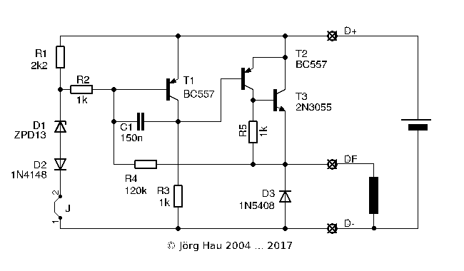
R4 is a feedback resistor that enhances the switching characteristics.
When you decrease its resistance, switching occurs steeper, but the
hysteresis window (i.e., the voltage that you need to reduce until
the circuit switches back on) is larger.
Capacitor C1 stabilises the circuit at higher load. I have observed that the switching behaviour
of the circuit without this capacitor is pretty "sharp" and stable if the load draws less than ca. 0.5 A (typically);
however at higher current I observed a tendency to oscillate.
This can be observed best with an oscilloscope, or a 12 V lamp as load: it will start to glow instead of being switched
completely on or completely off. C1 eliminates this instability; a value of 100 nF to 220 nF should do the job.
Diode D3 is to protect the electronics against induction currents,
which will appear when the current inside the magnetic field of the
alternator is switched. This diode is a fast-switching type which can
support 3 A. On my prototype, I have soldered another diode of the
same type across the C-E connection of T2 to provide some additional
protection (this is not shown in the circuit diagram or on the PCB
layout; the diode is just soldered on the copper side of the PCB).
Assuming you have enough knowledge to build the voltage regulator described above,
testing should not be a problem and is performed as follows:
Connect D- and D+ to the power supply's negative and positive line,
respectively. Then, connect a suitable load - for example a ceramic resistor
with about 10 Ω, or a 12 V/10 W lamp - between D- and DF.
The whole thing should be wired as shown in the figure. Connect a voltmeter
across the load (that is, between DF and D-).
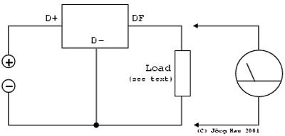
Now switch on the power supply and increase the voltage slowly. The output of the
voltage regulator should closely follow this voltage and the lamp (well, assuming you
use a lamp as load ;-) should light up.
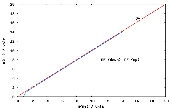
At about 14 V, the output voltage should drop to zero and should remain there,
even if you increase the input voltage further. It should come back if the voltage
drops slightly below the value found above.
An oscilloscope (instead of the voltmeter) comes in handy to test if the circuit
behaves stable around the switching voltage, or if it starts to oscillate.
To perform a vibration test of a voltage regulator, set the output voltage close
below the dropout voltage, then hit the regulator with a suitable tool, e.g. the plastic
end of a screwdriver. No dropouts are permitted. For heat testing, do the same but
heat it with a hair drier (but not too hot please).
What else?
As outlined above, the Bosch charging system in BMW "airheads" - and that
in many Moto Guzzi, let alone many cars - connects the field winding between
DF and D- (ground). However, you can use the schematic shown here also
with a system where the field winding is located "on the other side", that is,
between DF and D+: in this case you simply change all transistors from PNP
to NPN, reverse all diodes and swap D+ and D-. That's all!
From time to time I get e-mail asking "does your regulator also work in a
motorcycle with a permanent magnet" (or similar ;-). The short answer is
"no, it doesn't" - the way these alternators work is very different.
Their field winding is replaced by a permanent magnet and a too-high
voltage is cut off by shunting out one or more windings.
Here is a link a to voltage regulator circuit for shunt-type alternators.
Please do not ask me about it - I merely provide the link "as is"
for your convenience.
I frequently get requests about modifications of this circuit for use with
6-V alternator systems. Essentially, the only modification that is required
is to replace either D1+D2 by a single 6V8 type, or replace D1 with a 6V2 diode
and keep D2.
In addition, you may eventually want to reduce R1 to 1k2 ... that's all.
(Thanks to Tony Curnow for validating this ;-)
This information is provided in the spirit of "open design". The concept is
similar to that of open source software: It is available in "source form". Here,
this means that I am making the design information freely available and you
may use this information to build your own systems for personal use, free of
charge. However, if you wish to develop some commercial product based on the
information provided here, I require that you seek a licence from me first.
My aim is not to prevent you from making money exploiting this design
in commercial products, but to ensure that it remains a truly open model.
