Home |
Motorcycle Main page |
Links
"BMW Electrical" ?
Der Strom merkt immer, wenn kein Kabel da ist. - Ohm's 4th law
This page contains some information about the electrical system(s) of my BMW 2V motorcycles.
Most topics on this page were written from experiences that I made on my R80GS,
and some others relate more to the R100TIC. However, most of it should be applicable
to all BMW "airheads" - 2V boxer engines - from the /7 era onwards.
The usual disclaimer: I did these things with my own bikes and on my own risk, so if you repeat
this with your bike, you do it obviously on your own risk.
Technical note: Most of this was previously on the R80GS page
on this website, but due to the amount of material that page was getting too slow to load.
Early 2007 I decided to spread the material across multiple pages.
Charging System
Alternator diagnostics |
Changing the alternator |
Charging system data |
Diode board |
Links
Ignition system
Ignition coil |
Links
Starter motor
Accessing the starter motor |
Starter motor failure |
Replacement |
Preventive maintenance |
Repairing the Valeo |
Links
When working on the electrical system (except, perhaps, for changing a light
bulb), there is one golden rule: The ground cable of the battery is always
the first cable you disconnect and it is always the very last cable you
re-connect.
To paraphrase with the greek alphabet - it is the Alpha and the Omega.
Why? Well, in almost all cases the negative pole of the battery ("ground",
although this term is not physically correct here) is connected to the frame,
the engine block and the like. In other words, any metallic part of the bike
is connected to battery ground.
Now, imagine you want to unscrew the positive pole of the battery while the
negative is still connected.
Sooner or later in this process, the wrench (which is tightly "clamped" to
the positive pole) will accidently touch a part of the frame, a mounting
bracket or something similar ... which means, you will have a nice short
circuit between battery plus and battery ground!
If you are lucky and react fast, you may be able to withdraw the wrench,
but there have been reports of wrenches that were first "electrically soldered"
to the frame and then melted within a few seconds. I'm pretty sure you would
like to avoid that kind of experience ;-)
At this point, you might know that a fully charged battery of 25 Ah can
deliver 25 A for one hour, or - approximately - 250 A for about 6 minutes.
250 Amperes is quite a huge current: the starter motor of a BMW 2V boxer
can draw up to 130 A, which is the reason for such a fat wire between battery and starter.
It seems that my GS "consumes" an alternator about every 50000 to 60000 km.
The first time this happened was in 1993-10, at about 61'000 km.
I had stopped somewhere for shopping, then went back to the bike,
turned the key and pressed the starter button.
"klick-klick".
Well ... that was the noise of the starter relay. The battery was too weak to
turn the starter motor and in turn to start the engine. Fortunately, I could
start by pushing the 220 kg, but the charge control light was smiling at me.
Riding to the BMW shop nearby, diagnosis was clear: The alternator winding
was open.
Changing it is fairly easy, but the part itself costs a few bucks ... about
150 DM in 1993. This was a re-built exchange part, as the original part was
not available within a reasonable delay.
The second time this happened was a only few months later, at about 68000 km.
I was in Paris for a weekend, stopped at at little shop to buy something, then
went back on the bike and pressed the start button ... "klick-klick".
Bad, very bad for your holidays. Well, what do you do? First of all, get the
bike running again. I opted for the run-and-jump method ... of course with a
well-loaded bike and bags. I never thought that these bags could hinder me,
but if you have to run besides your own bike they are really, really in the way!
Later on I went for troubleshooting. I knew that the battery was not longer
charged correctly, but I could not really find out what was wrong and the BMW
shops are relatively rare in France.
However, I managed to go for several hundreds of kilometers like that until I
was home. The important thing is to make sure you use jump start every time,
and that you do not consume too much current (during the day I rode with the
parking light instead of the headlight to save energy). The problem with all
modern bikes is that they are full of electronics and once the battery is
empty you are lost. Magnet-induced ignition would be nicer ;-)
I have been searching the source of this problem for several weeks later on.
The voltage changed considerably with engine temperature (13.6 V at
4000 rpm when running in 5th gear, dropping to 12.6 V at
4000 rpm with hot engine).
The charging light would light up when I turned the ignition on, but would not light
up when riding, so everything looked well - but it was sure that the battery was
not charged correctly. I checked the voltage regulator, the diodes, but no clue ...
no, it couldn't be the alternator winding, that part had been changed just a few
months ago ... but then I obtained the electrical values for the alternator winding!
It should have a resistance of 3.4 Ohms, but it actually was only 1.2 Ohms.
In other words, this was a partial short circuit of the winding!
- It turned out that the problem was due to the rebuilt part; I got a new one (partially
under warranty) and this time it was the original BMW part for 340 DM (1994).
 The really weird thing in this case was that the charge control light would not light
up, but the battery would not be charged correctly either - in other words, no warning,
but you loose energy. This is a situation when a voltmeter on the bike would have
been truly useful ... indeed, a few years later I installed such a device.
The really weird thing in this case was that the charge control light would not light
up, but the battery would not be charged correctly either - in other words, no warning,
but you loose energy. This is a situation when a voltmeter on the bike would have
been truly useful ... indeed, a few years later I installed such a device.
As I said, the bike eats up one alternator about every 50...60000 km, so
the next rotor was due at about 103900 km (1999-09). This time it was a "nice"
failure, with the charging light coming up and the rotor having a real
interrupted winding. Nothing special to tell, but it cost me about 320 CHF.
Do this with a cold engine. You will need three "special" tools:
a hardened steel rod 6x50 mm, an allen screw M8x30 and ... a hammer.
As an alternative to the steel rod/allen screw combination, you may get
an M8x100 bolt and turn the "outermost" 50 mm of thread down to
a diameter of 6 mm.
- Disconnect battery ground (and isolate that battery pole).
- Unscrew and remove engine front cover (2 screws).
- Write down stator winding cable contacts.
- Disconnect stator winding cabling: black cable on Y (right side of the
engine), brown on D+ and black on DF (on top), black and white and red
on D- (bottom left, from top to bottom).
- Move up the coal brushes and fix them in this position (using their springs).
Check them and replace if they are too short.
- Unscrew the three screws holding the stator winding, then remove it.
You may need to use some tool (e.g. the key to adjust the rear shock)
as a lever to remove it as it sits quite "snug" over its frame.
Note that the stator includes the aluminium "cover" and
the copper winding below (see picture),
so please be careful.
- Remove the center screw of the rotor (put the engine into 1st gear to block,
eventually have someone stand on the rear brake).
- Slip a (hardened) steel rod of 6x50 mm into the center hole. Then, use a M8x30 screw
(preferably with Allen head) to push against this steel rod. When the screw is sitting
firmly (you feel the tension), give it a short but well-dosed "smack" with the hammer
along its axis. The alternator rotor should come loose and can be removed easily.
- Insert the new alternator and fix it with its original screw (25 Nm).
- Re-install parts as above.
- Check twice for correct cabling and well-fixed screws.
- Put gearbox into neutral.
- You may want to test the engine now. Connect a voltmeter (e.g. to the
12 V plug) and make sure you get 13.6 V as soon as the engine
runs at 2000 rpm or more, even with the headlight on.
- Have fun.


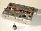
(Left) The engine cover removed. (Right) Alternator stator, alternator rotor, rotor holding screw,
and the "special tool" to draw the rotor.
If your charging system is OK, you must get a voltage reading of 13.6 V or better
above 2000 rpm with the headlight on (!). Not more than 14.5 V.
The charging system is supposed to be working from 980 rpm onwards.
Alternator rotor, new, across the contacts: 3.4 Ohm (± 0.3 Ohm).
The part number of the alternator rotor is: BMW 12-31-1-244-642 (Bosch 1-124-033-031),
which fits all 2V boxer engines from 1969 to 1994.
It seems that there exists a reinforced version (for police bikes etc.) with part number
12-31-4-257-539, but I don't know any details about this.
To control the stator: Measure contacts U, V, W against each other. Reading should
be around 0.6 Ohm (less than 1 Ohm in any case). Must be isolated against ground.
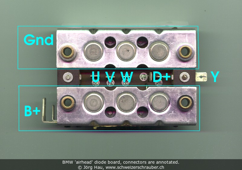
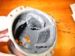
You may test the diode board either with a small test lamp or with any Multitester.
The wiring diagram for the diode board is shown in your rider's manual and the
following picture shows the diode board of my GS at 110'000 km.
The device was scanned from the back so that all connectors are visible; the colors were somewhat falsified by the scanner.
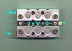 Note that the D+ connector has two pins, you can use either of them.
Another important thing is that the upper part of the plate connects to battery ground,
while the whole lower part is directly connected to the positive pole of the battery (B+).
Take care to verify insulation of the rubber parts around the bolts!
Note that the D+ connector has two pins, you can use either of them.
Another important thing is that the upper part of the plate connects to battery ground,
while the whole lower part is directly connected to the positive pole of the battery (B+).
Take care to verify insulation of the rubber parts around the bolts!
The following table shows the values that you should obtain when you test the
diode board (which has of course to be removed from the bike to be measured).
O means "open", X means "conductive".
If you have a diode tester, the connections marked with XX
should show twice the voltage of the X-rated ones
(yes, there are two diodes in the path).
Please note that some Multitesters inverse the voltage on the test probes
when they are operated as Ohmmeters, so before you conclude that a
diode is defective just inverse the leads and test again.
| |
Positive test lead on |
| B+ |
GND |
U |
V |
W |
D+ |
Y |
| Negative test lead on |
B+ |
- |
XX |
X |
X |
X |
O |
X |
| GND |
O |
- |
O |
O |
O |
O |
O |
| U |
O |
X |
- |
O |
O |
O |
O |
| V |
O |
X |
O |
- |
O |
O |
O |
| W |
O |
X |
O |
O |
- |
O |
O |
| D+ |
O |
XX |
X |
X |
X |
- |
O |
| Y |
O |
X |
O |
O |
O |
O |
- |
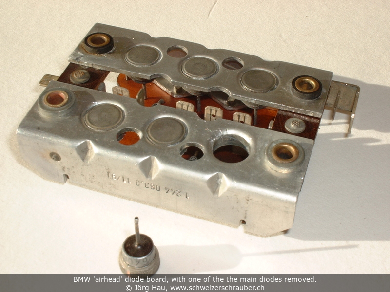
As a side note: The small diodes are BYW72, the big ones Bosch
1405-0241 and 1406-0241, or 405.426 and 406.424 (three each).
Reportedly, these can be replaced by Motorola 1N3660 (cathode to case)
and 1N3660R (anode to case), which are rated 100 V and 30 A at 100 °C.
The function and testing of the Bosch-type voltage regulator are described
on its own page, also on this site.
A simple 2-LED "voltmeter" to survey the health state of the charging system, also on this site.
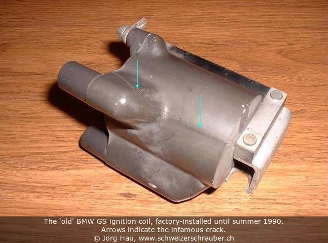
It seems that the grey ignition coil of the earlier GS models has a
design flaw that causes the coil to crack after some years of usage.
In summer 2001 I found that mine had a crack, too, but I only noticed
this in a heavy downpour (what else?), when the engine suddenly stopped.
After a few minutes I could start again, arrived home and upon closer
investigation I found a fine "line" running along the body of the coil.
 I first mistook this for a residue from plastic moulding, but it was indeed
a crack, allowing water to enter the coil. With the remaining heat of the
engine, the water would evaporate and allow to start again after a few
minutes.
I first mistook this for a residue from plastic moulding, but it was indeed
a crack, allowing water to enter the coil. With the remaining heat of the
engine, the water would evaporate and allow to start again after a few
minutes.
This crack (nicely visible in the upper image) caused the
secondary (HV) coil to break - I measured
"infinite" resistance between connectors 4a and 4b - but the bike would
still run without problems for several hundreds of kilometers, if weather
was dry! It seems that the high voltage generated was enough
to bridge the broken winding inside the coil and all that even without
causing excessive heat (not more than hand warm). However, after a
few hundred km the idle started to degrade and the replacement coil arrived
just in time.
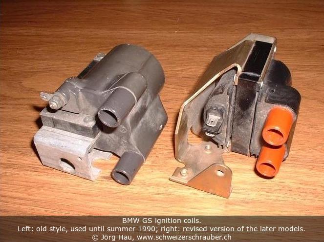
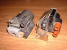 Looking for a spare part I found that BMW had redesigned the ignition
coil several times and it seems that the new model is more durable.
Price for the new coil was about 190 CHF in summer 2001, but I decided
to get a used one. The photo shows the old design (left) side by side
with the revised version (right).
Looking for a spare part I found that BMW had redesigned the ignition
coil several times and it seems that the new model is more durable.
Price for the new coil was about 190 CHF in summer 2001, but I decided
to get a used one. The photo shows the old design (left) side by side
with the revised version (right).
Electrical data: For the "old" (gray) coil, resistance between 1 and 15
(primary) should be about 1.1 Ohms, between connector 4a and 4b
(secondary) 7.5 ... 9.15 kOhms. The revised version (red) has
0.5 Ohms primary and 12.8 kOhms secondary.
Spark plug with cable, 5 kOhm.
The BMW airhead ignition coils have a rather "special" design: the secondary coil
is not connected to the primary coil but both ends are free floating. This works
pretty well, but it has the disadvantage that the spark on one side jumps from the
center electrode to ground and on the other one from ground to center.
If one of the spark plugs gets dirty, if draws current off its counterpart.
A solution for this problem is to use the classical construction for ignition coils,
where the primary and secondary winding are connected to each other. One such design
is the "TwinCoil" from Silent Hektik, which I installed in 2001-09 (111'800 km).
It uses one common primary winding and two separate secondary windings, both of which
are connected in parallel to the primary coil. In this way, the spark always jumps
from the center electrode towards ground.
This change brought a better response to the throttle and I have the
feeling that the cold starting behaviour has improved, too. -
Electrical data (for quick testing): primary 2.1 Ohms, secondary 12.3 kOhms each,
cables about 2 kOhms each. I don't know their factory tolerances.
- Bosch
ignition module replacement (Link seems to be dead).
This part has also been used in many cars, e.g. in the following VW/Audi (part number
191 905 351b): VW Golf 79-89, VW Passat 79-89, T2 Transporter 79-92,
Audi 100 80-93, Audi 80 79-93, Audi Coupé 81-94, VW Caddy 83-92,
VW Scirocco 79-95, VW Corrado 79-95, VW Jetta 79-92, VW Vento 79-92.
Many Thanks to Klaus "oelzeug" for the compilation of this list!
-
Testing the ignition module and
the ignition trigger can, and
repairing the BMW Ignition Trigger Unit.
- A simple Hall effect sensor tester by Robin Frankham (Link seems to be dead).
By the way, the hall sensor used in the 2V BMWs is a Honeywell 2AV54.
- Frank Warner's text (.doc format) on
fitting a second Hall Effect Sensor inside the Ignition Impulse Sending Unit (for models from 1981 onwards).
At about 110 Mm, I noticed some unusual noise as the engine fired up.
Everything essential was OK, but there was a loud "screetching" noise for
about one second when the starter should release the flywheel.
I thought that it might have been a lack of grease in the starter, causing
it to stay with the flywheel when it should release and decided to
disassemble it before things would get worse.
Special tools required: A very short, compact tubular wrench or ratchet
13 mm. If you want to dismantle and grease the gearing, get a
"T20" torx screwdriver and silicon grease (see below).
- Remove seat and gas tank.
- Remove the ground cable of the battery (and isolate that battery pole).
The starter motor is connected directly to the positive pole
of battery and there is no fuse, so any short circuit in this area
will be a "hot" disaster!
- Remove the top engine cover (2 screws, slide it backwards and lift it
off to the side). You now see the starter motor.
- Remove the three wires that go to the starter motor, two with "heavy load"
contacts (one directly from the battery and one from the diode board that
is used to charge the battery) and a third one just below (this one goes to
the starter relay, which in turn activates the starter solenoid).
Take care not to damage the copper parts, as they are pretty soft.
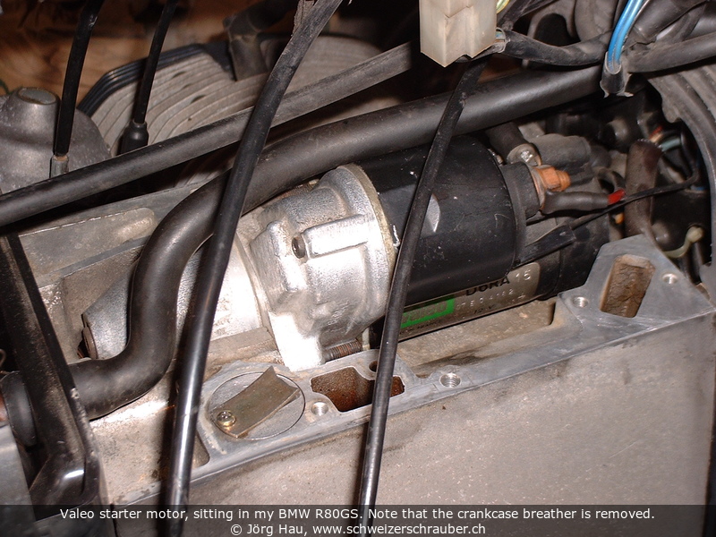
- At the front of the top engine cavity, there is a rubber hose that
goes back to the air filter. This will block the starter motor and should
eventually (but not necessarily - it depends if the rubber is still elastic)
be unscrewed, either at the clamp or at the base plate.
Put a piece of clothing here to prevent dust or pieces going in there.
- The starter motor is held in place with two bolts M8x45 and that is where
I started to doubt about the ingenious BMW engineers: Space is extremely
confined here and you need a very compact, short 13 mm ratchet wrench
or something similar. This is not a difficult task, but very tedious ... it helps
to unscrew the two bolts simultaneously and to push the starter motor
forward after every turn while you fight with the bolts, so that you have
a maximum of space available.
- Now you can lift the starter motor out of the upper cavity, giving
you a nice view onto the flywheel and the clutch area. While
you're at it, clean this area from dust, grains, dead insects, ...
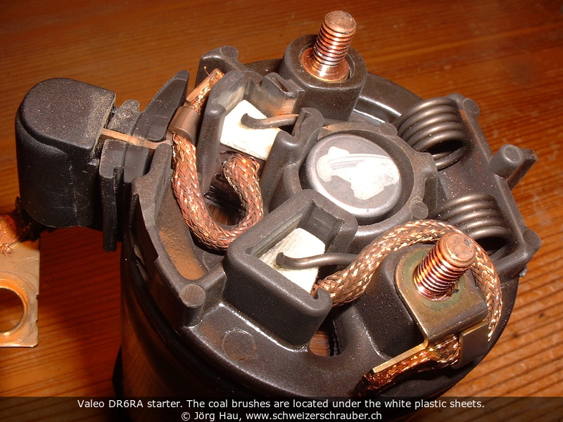
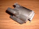
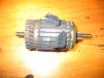
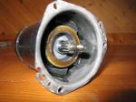
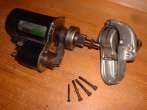
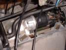 My GS has a "Valeo" starter, type DR6RA-15. It is composed of three main parts:
The starter motor itself - big black cylindrical part -, the magnet switch -
smaller black cylindrical thing with two big copper contact screws - and the
"gearbox", which is the conical aluminium cover that goes over the flywheel.
My GS has a "Valeo" starter, type DR6RA-15. It is composed of three main parts:
The starter motor itself - big black cylindrical part -, the magnet switch -
smaller black cylindrical thing with two big copper contact screws - and the
"gearbox", which is the conical aluminium cover that goes over the flywheel.
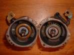
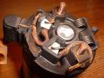
To inspect the coal brushes, unscrew the two little copper screws
on the (big) motor housing and withdraw the "end cap". This part may seem
to be stuck, but it isn't - it has a very tight rubber seal and comes off
smoothly when you pull gently.
Do not pry with a screwdriver or other tools - the plastic part that holds the brushes is rather fragile.
The interior should be clean and almost free of dust. -
Now, inspect the brushes. On my GS, they were in excellent shape and
2+ cm in length although the bike had gone 110000 km at that time.
Nothing to do, so I put it together again.
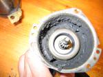
To grease the starter "gearbox", remove
the aluminium cone (three allen keys plus a T20 torx key. Unfortunately
you cannot replace the latter with an Allen-head bolt as it has a special
threading!). Clean the parts and grease the windings with silicon grease.
The BMW manual specifies Bosch PZ2V3; as I did not have this at hand I took
temperature-resistant silicon grease from the chemistry lab (Molykote 111).
Then, reassemble the parts.
... and that's all. Reassembling goes exactly in the reverse order.
As for those infamous mounting bolts, you may want to replace them with two
Allen-head bolts M8 x 45. Reportedly it is even more convenient
to swap the two bolts that hold the starter motor with those that attach the
bottom of the air filter housing, allowing you to remove both the starter motor
and the bottom of the air filter housing much easier ;-)
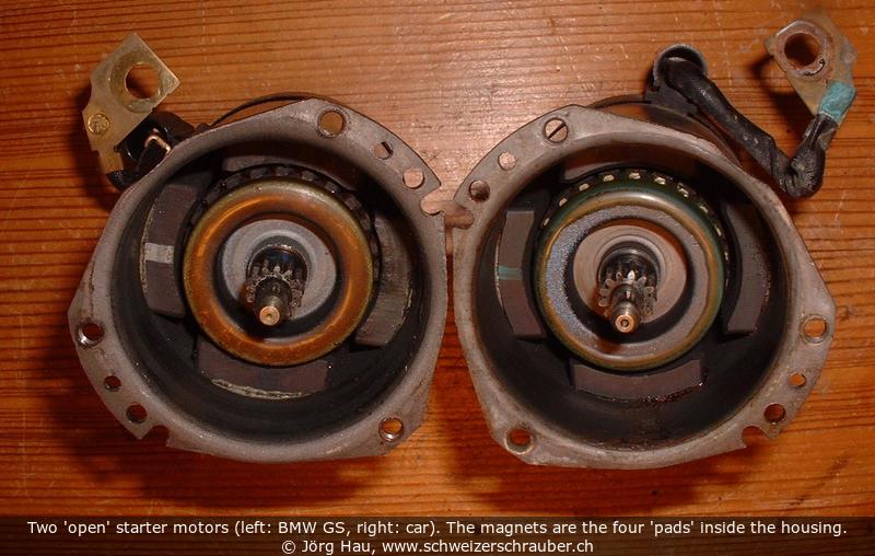
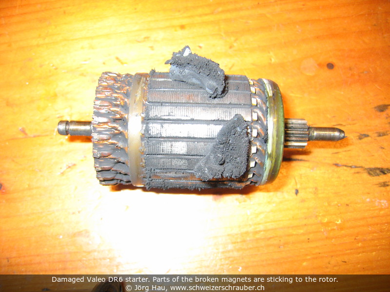
Most Valeo starters tend to fail over time, due to "lost magnets". I experienced this on my GS in summer 2016.
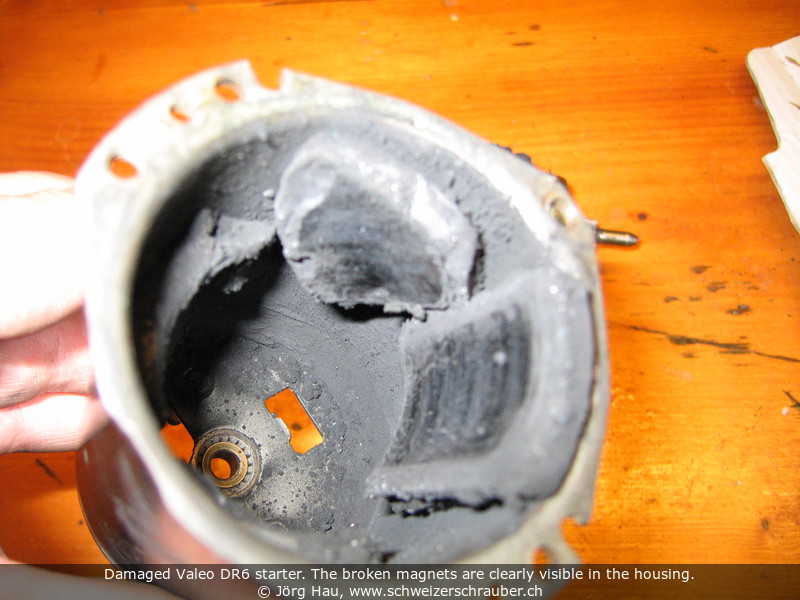
These magnets are part of the starter motor itself and are glued to the outer part of the housing.
Over time, they may simply fall off, probably due to thermal and/or mechanical stress.
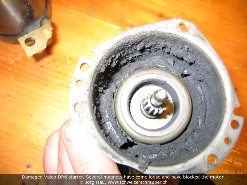
Loss of one or two magnets may go unnoticed at first, but the resulting debris will block the starter motor in the most inconvenient moments.
The symptoms for the "magnet failure" are somewhat similar to the symptoms of an empty battery,
but there is a subtle difference of the noise when you press the starter button:
- If the problem is related to an empty battery, you will usually hear a "klick-klick",
eventually followed by a rattling "krrrrr" noise.
- If the problem is related to the magnets, you will hear a single "klick", then the lights will go dark. No rattling.
In the latter case, the starter motor is blocked and the magnet debris is blocking the rotation.
Do not re-re-try to use the electric starter: it, or its cabling, will overheat!
Note that you can still ride the bike — you just have to prepare for jump starting, e.g. by parking downhill.
We spent a whole weekend doing this, two-up and loaded with luggage ;-)
It is possible to repair such a defective starter by reattaching the magnets (see the links at the end of this section). However,
unless you are stuck in a remote place, it is probably more efficient to replace the complete starter motor, or to re-use parts from a car junkyard.
Probably the simplest alternative is to buy a new starter: as of 2016, prices for China copies of the original Valeo Starter
have dropped to and below the 100-EUR range. Many of these replacement motors feature brackets that secure the magnets in place,
in addition to the glue. You may want to look for those.
In 2016-06, I replaced the failed starter motor of my GS by such a brandnew motor, obtained from
auto-elektrik.de (underlying domain is no longer active?).
Carsten Tiedemann, the company's owner, takes the "raw" China copies and reworks them so that they should last.
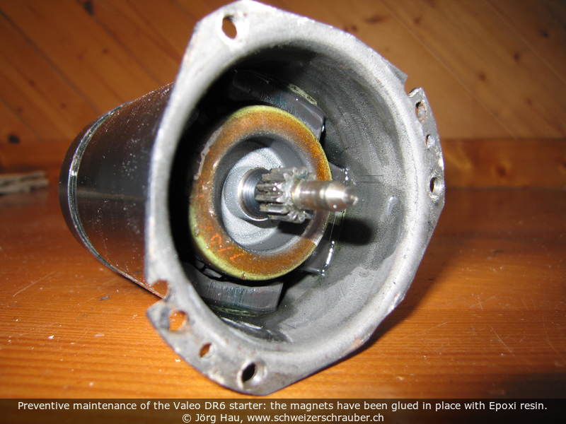
If your Valeo starter is still working well, you can perform preventive maintenance:
Open the housing, remove the rotor and then glue the four magnets in place with a strong, thermally stable glue.
I have used epoxy resin for this - the same resin that I use for the weather-proof casting of electronic compounds.
Of course, the process had to be done in four steps, leaving enough time for the resin to cure and then rotating the housing 90° after each step.
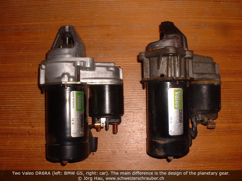
Another possibility is to scavenge parts from another starter, obtained from a car junkyard.
Valeo starters of the type we need were used in a number of smaller cars, such as Opel Corsa, Astra, Kadett;
Renault Clio; Citroën AX, BX and C15; Peugeot 205, 206, 306, 307, 309, 405, etc.
Those who live in the USA may want to look for Saturn cars.
Do not worry too much about the shape of the cast aluminium cone; the important point is that you ask
for a Valeo DR6RA or DR6A.
(It seems that the starter of the Renault Laguna is even a true 1:1 replacement for the complete BMW part?)
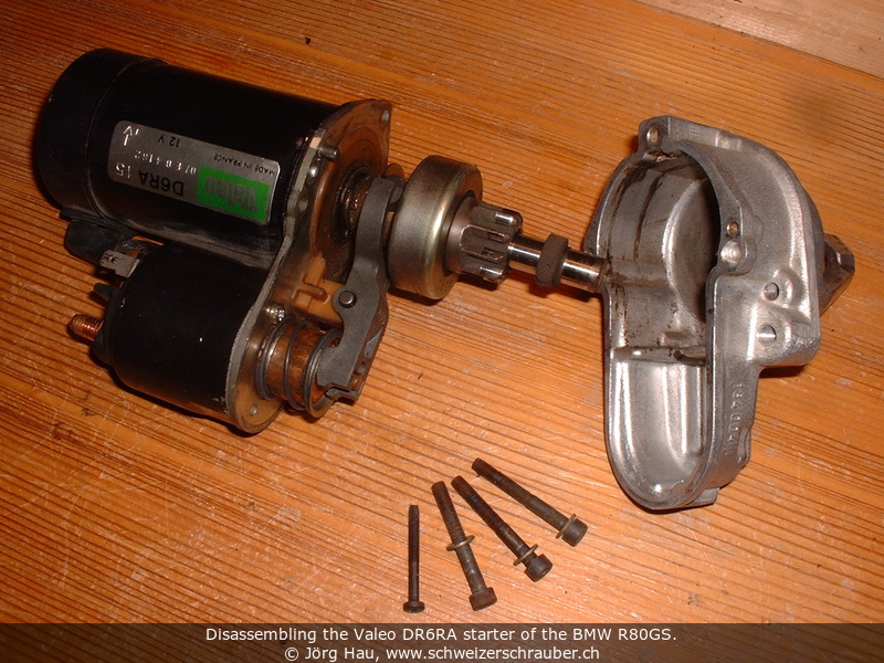
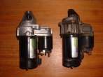
The part swap is pretty straightforward. On both starters, proceed as follows:
- Remove the starter from the bike, as described in the previous section.
- Remove the starter "gearbox" as described (three Allen-head bolts, one Torx T20).
At this point, you will notice a big similarity between the two assemblies;
the major "visual" difference is indeed the aluminium-cast housing of the planetary gearbox "nose".
It is tempting to do a "quick swap", but be careful: count the number of teeth on the cogwheel;
you will need exactly 9!
- The starter motor housing is attached to its base plate with two rivets. Drill them out.
- Unscrew the short, thick wire that is connected to the starter solenoid (13-mm key).
- Carefully withdraw the motor from its base plate.
- Clean out the dirt that is eventually present, then swap the starter motors.
- Reassemble in reverse order ;-). You do not need to replace the rivets, since the three
Allen-head bolts will hold the complete unit together.
- An article on
Alex's pages may be helpful - there's information on Valeo starters, in particular re-attaching the magnets.
- Anton Largiader
has also a good description on Valeo starter overhaul, with many photos and diagrams.

 The really weird thing in this case was that the charge control light would not light
up, but the battery would not be charged correctly either - in other words, no warning,
but you loose energy. This is a situation when a voltmeter on the bike would have
been truly useful ... indeed, a few years later I installed such a device.
The really weird thing in this case was that the charge control light would not light
up, but the battery would not be charged correctly either - in other words, no warning,
but you loose energy. This is a situation when a voltmeter on the bike would have
been truly useful ... indeed, a few years later I installed such a device.